Products for CNC and
motion control applications since 1998.
Design, manufacturing, and support based in the USA.
Click here to see what our customers say about PMDX
We save you money with our $13.00 flat rate Priority Mail shipping for most domestic orders.
General Information
FIND PRODUCTS:
Select Below
To Browse
- Listed by Number (All)
- PMDX-340 CNC Control Box
- Motion Controllers
- Breakout Boards
- Extra I/O & Isolation
- Power Sources
- Test & Development Tools
- Spindle Controllers
- Panels, Pendants & MPGs
- Contactors, Breakers,
SSRs & Power Switches - Noise Filters &
Common Mode Chokes - E-Stop & Control Switches
- Cables & Parallel Ports
- Connectors & Misc
- Software(Mach4,Mach3 etc.)
- Legacy Products
Our Most Popular Products
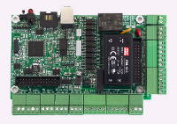
Model PMDX-125
Multi-Mode Breakout Board
The PMDX-125 has been replaced by the PMDX-126.
The PMDX-126 is an upgrade of, and a direct replacement functionally and mechanically for the PMDX-125.
Click here to see the PMDX-126.

PMDX-125 board pictured as delivered.
(click on image for higher resolution version)

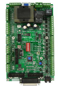
PMDX-125 pictured with PMDX-107, SmoothStepper, and cables.
(click on image for higher resolution version)
The PMDX-125 is a motion control breakout board for interfacing with the parallel port of an IBM-PC style computer or to the Smooth-Stepper.
PMDX now offers Gecko G203V, and G320X motor drivers at a discount. For more info see HERE.
Features of the PMDX-125
- Connects to host using a single DB-25 Female parallel port connector when using port sharing modes. Additional 26 pin ribbon headers support use of a second parallel port or direct connection to a SmoothStepper. The second SmoothStepper port supports 4 input and 4 output signals. The remaining 8 data bits of the second SmoothStepper port can be supported as input or output by adding a PMDX-108-Input or PMDX-108-Output board.
- Supports all signals present on the primary standard printer port. (8 data, 5 input, 4 output)
- Supports 4 additional high speed inputs using multiplexed I/O, or a second parallel port, or the second port of the SmoothStepper
- Supports 4 additional high speed outputs using a second port or the SmoothStepper
- The additional high speed outputs can be used as step and direction for greater than 4 axis operation when using two ports or the SmoothStepper
- Can also support the 4 additional outputs at low speed using bit stream I/O on a single port
- Mach software plug-in and EMC sample HAL files provided to support enhanced I/O features
- On board LED indicators on all signals
- Terminal strip outputs provided for external LEDs showing status of Power On, E-Stop, Charge Pump, and step signal activity
- Connector for future remote display of status and control signals
- All status inputs are optically isolated
- All parallel port signals are terminated and filtered to help resist noise problems
- All step, direction, and control output signals are buffered with 16 mA drivers
- Special isolated interface to sense ERR/RST signal used by Geckodrive servo products
- Special isolated interface can reset and enable Geckodrive servo products from the computer
- E-Stop, Fault, ERR/RST, and "Charge Pump" timeouts turn off all outputs without assistance from host software
- Provides one 30 ampere rated electromechanical relay useful for spindle control
- Provides one 10 ampere rated electromechanical relay for auxiliary functions
- Relays have MOV arc suppressors for longer life of contacts
- Can directly connect with and provide power for PMDX-104 to provide 4 additional relay outputs
- Powered directly by AC mains 115 or 230 volts, switch selectable
- Self resetting poly-fuse protects mains power input
- Can provide +5 power to SmoothStepper through ribbon cables
- Can mount SmoothStepper as a daughterboard using standoffs
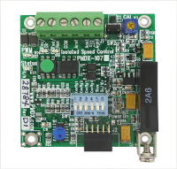
- Has provision for option card mounting directly or using a ribbon cable to the PMDX-106, PMDX-107 spindle speed controllers and other future products
- Screw terminal blocks with Step, Direction, +5 volts, and Ground for outputs to drivers
- Buffered step and direction available as ribbon header for connection to driver boards with ribbon header inputs for parallel port signals
- Screw terminal blocks for isolated status inputs also provide +5 volts and +12 volts to power sensors such as the PMDX-170, PMDX-171, and NPN proximity sensors
- Status sensor inputs work with mechanical switches, NPN sensors, 5 volt logic signals, and are 24 volt tolerant
- Inputs expect a "sinking" drive signal to activate them by pulling the input to ground. Inputs will tolerate up to 24 volts DC in the inactive state to allow use in PLC and relay logic systems with 24 volt power. If a "sourcing" signal (like a PNP sensor) must be used, please see the PMDX-105 Quad Isolator/Translator.
- Pulse stretch circuit to allow narrow pulse encoder outputs to be used as lathe index signal
- Built in test for generating step signals without need of a host computer
- Built in test step signals run at proper speed for Geckodrive stepper driver smoothness adjustment
- "Charge Pump"/watchdog function has enhanced timing algorithm to avoid teasing by Windows boot process
- Designed for easy interconnection with PMDX-104 and PMDX-108-Output to provide solid state isolated outputs to connect with PLC systems, and power contactors
- Designed for easy interconnection with PMDX-108-Input to provide 8 additional isolated inputs when using a second port parallel port or SmoothStepper
- Microprocessor and programmable logic allow for the future addition of more features
PMDX Breakout board feature comparison table
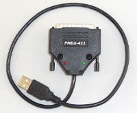
Note: The step and direction signals used to run this board as a real time CNC device require precise timing. These signals are normally provided by a personal computer motherboard with an onboard parallel port, a parallel port interface card plugged into a motherboard with ISA, PCI, or PCI-Express slots, or by an external device such as the SmoothStepper. You cannot use a USB to printer adapter because it will alter critical timing of CNC control signals. Laptop computers, even those with parallel port interfaces, are not recommended as CNC control computers due to design features that can alter critical timing. If you must use a laptop be prepared to deal with these design issues and/or plan on using an external pulse generating device such as the SmoothStepper.
Download the full manual in PDF format here
(revision 1.2, 26 Feb 2010, 314 KB).
NOTE: This manual is for board revision "D5" and later (i.e. higher letters/numbers).
For earlier PMDX-125 board revisions, see our User Manual Archive
Click here for application notes on using the PMDX-125.
Copyright 2004-2022